

Warning, following these instructions may cause injury or damage or cause a black hole to suck everything we know into oblivion.
Ingredients list:
1. Wireless winch remote controller.
2. A package of crimp connectors.
Tools list:
1. Large Slotted screwdriver
2. Tiny slotted screwdriver
3. Wire Stripper
4. Wire Crimper
5. Adjustable wrench or socket set.
Steps:
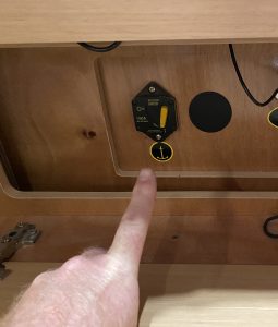
1. Turn off the Windlass breaker located under the owners bed near the battery disconnect.
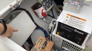
2. Open the windlass solenoid enclosure just forward of the generator inside the generator locker.
3. Cut off the ring terminals on the black, yellow and white wires of the new wireless remote.
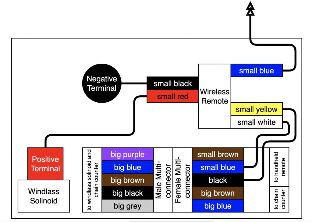
4. Crimp a 5/16” ring terminal onto the black wire of the new wireless remote.
5. Crimp a 5/16” ring terminal onto the red wire of the new wireless remote.
6. Loosen and remove the nut on negative terminal in the windlass control box.
7. Install the black wire from the new wireless remote control onto the stud and re-attach the nut to the negative terminal.
8. Loosen and remove the nut on positive terminal in the windlass control box.
9. Install the red wire from the remote onto the stud and re-attach the nut to the positive terminal.

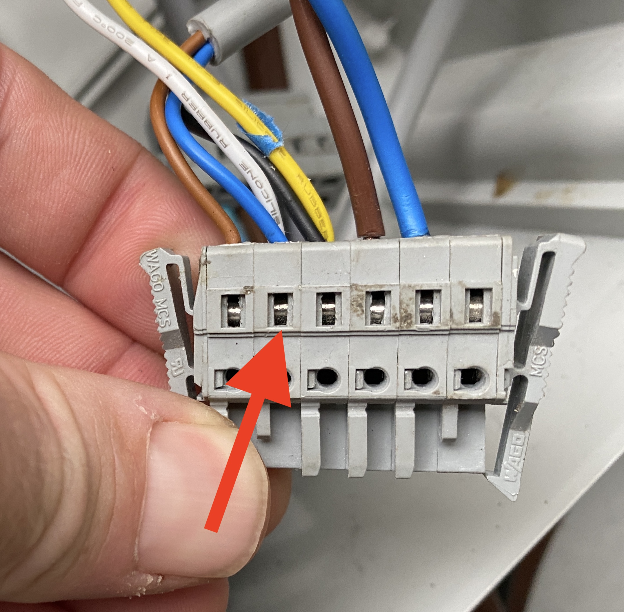
10. Remove the small blue wire from the female multi-connector using a small screwdriver to open the jaws of the connector.
11. Add the small white wire from the new wireless remote to the blue wire you just removed and replace it in the jaws of the connector.
12. Remove the small black wire from the female multi-connector using a small screwdriver to open the jaws of the connector.
13. Add the small yellow wire from the new wireless remote to the blue wire you just removed and replace it in the jaws of the connector.
14. Make a small hole in the enclosure for the small blue wire from the new wireless remote to exit. This is the antenna.
15. Turn power back on to the windlass via the breaker in step 1.
16. Turn on the handheld remote control and press the up and down buttons to control the windlass.
17. Replace the cover on the windlass solenoid enclosure.

2 Comments
Points 11 & 13 both mention blue wire from lagoon original install – is this correct?
Additionally, I believe that brown & blue wires are the “control” wires & should connect to yellow & white wires of wireless remote. Isn’t black wire shown in photos below point 9 & 13 the negative wire?
Thoughts?
You would think that. I went through the entire thing including shorting between each contact to see the reaction from the windlass. I even took apart the wired remote to find that the brown cable was the common (ground).
I don’t think they followed “standards” for that cable as it is a control cable and not a primary conductor.